The containment spray heat exchanger plant is 12.4 meters long。
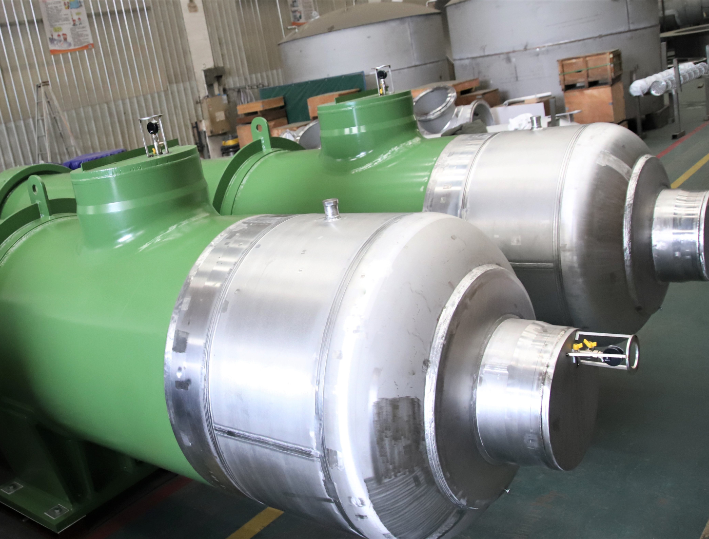
The containment spray heat exchanger is a horizontal shell and tubeheat exchanger supported by two saddle supports.The containment spray heatexchanger consists of the following components:
PART1 Shell
The housing material is carbon steel
The two cylinders are connected by an expansion joint to form ahousing assembly. The two sleeves of the expansion joint are welded to thehousing, the 5-wave elastic bellows are connected between the two bushings, andthe 12 tie rods act as guides when the expansion joint moves axially. The twoends of the shell are welded with two tube plates, the entrance of the shellside has an anti-impact baffle, the anti-impact baffle is welded to twofixed-distance tubes and a support, the support is part of the shell, and theanti-impact baffle prevents the inlet fluid from impacting the tube bundle andcausing the tube to vibrate. The housing of the heat exchanger is connected tothe chilled water system via nozzles c and d.
PART2 Discipline
The heat exchanger bundle material is austeniticstainless steel.
The heat transfer tube is welded through thesupport plate, baffle plate and expanded to the tube sheet at both ends of thehousing. The baffle plate and the support plate are kept at their respectivedistances by the fixed distance tube, 12 tie rods pass through the fixeddistance tube, one end is tightened on the tube plate, and after the fixeddistance tube, support plate and baffle plate are installed, the other end ofthe tie rod is tightened with a nut and spot welded to the last baffle plate.The back of the tube sheet at both ends of the housing is welded to the housingof the heat exchanger and the front is welded to the water chamber cylinder.
PART3 Inlet water chamber
The inlet water chamber consists of thefollowing components
· A cylinder welded to a tubesheet
· A head welded to the cylinder
· A handhole g with a cover plate
· Inlet water chamber drainnozzle f
· Inlet water chamber exhaustnozzle J
· Spray water inlet nozzle A
PART 4 Outlet water chamber
The outlet water chamber consists of thefollowing components
· A cylinder welded to a tubesheet
· A head welded to the cylinder
· A handhole with a cover plate h
· Outlet water chamber drainnozzle e
· Outlet water chamber exhaustnozzle i
· Spray water outlet nozzle B
PART 5 Supports
The heat exchanger is supported by twosaddle bearings welded to the equipment housing. The saddle support is fixed byanchor bolts to the foundation of the heat exchanger. A saddle support close tothe inlet water chamber is fixed to the foundation, and the other saddlesupport can be displaced axially relative to its foundation to compensate forthe expansion or contraction of the heat exchanger.